

Figure 1: 1950’s press converted to a modern clutch brake
Common Clutch Mistakes
There are a large number of presses still in production that were built in the 1940’s to the 1970’s. Typically these are well designed, heavily built machines. Most of these machines benefit greatly from updating to a modern clutch/brake assembly.
The modern clutches provide better performance and reliability compared to most clutches built before 1980. Better stop times, lower maintenance requirements, and better availability of spare parts adds up to lower cost of ownership and increased productivity.
Over the last 40 years I have engineered hundreds of clutch conversions and inspected thousands of clutch installations. Below I discuss the three most common mistakes that I have made or witnessed on clutch conversions. These mistakes are the most Common ones I have seen which have a significant negative impact on performance and reliability.
Since the late 1970’s vast improvements have been made in the combination clutch/brakes available. I will refer to these as “Modern” clutches. Clutches built from the 1940’s to late 1970’s, I will refer to as “Old Style” clutches.
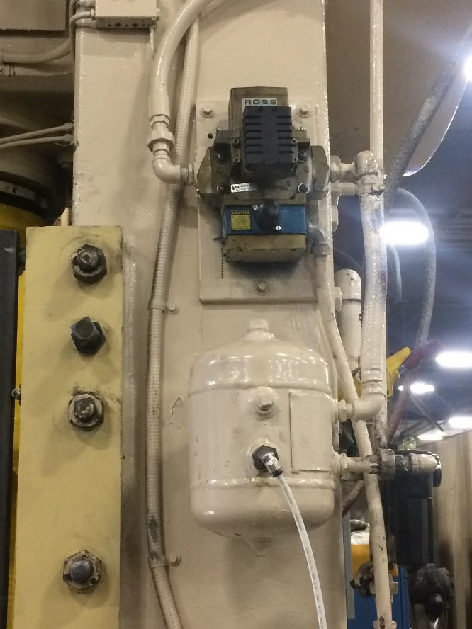
Figure 2: Accumulator Tank is Too Small
1. Air System Sizing on the “Old Style” clutches typically required 60 to 65 psi compressed air in relatively low volume for optimal performance. These clutches had multiple friction discs and lower brake spring pressures so they required the lower air pressures. Brake stop times were not measured in milliseconds so stopping performance was not a major consideration. “Modern” clutches with their larger pistons and higher spring pressures are doing more work with less parts. They require 75 psi to 85 psi compressed air in higher volumes. Production rates have also increased leading to higher air volume requirements.
In Figure 1 and Figure 2 we see a 1950’s press that has been converted to a new style clutch but the air system was not updated. Originally this press had a clutch with a rubber diaphragm used to operate the clutch piston. It used very little travel to engage. This clutch required less air to operate, but also required frequent adjustments to maintain proper clutch travel. From the size of the air tank I believe this press was originally designed to run production in the continuous mode. The original clutch was fine with a one inch Press Safety Valve and a three gallon accumulator tank.
Today this press has a modern clutch and is being single stroked at 12 times per minute. The “Modern” clutch has a much larger piston that is allowed considerably longer travel before requiring adjustment. For the new clutch to perform at its rated capacity it requires a significantly larger air system. The piping for this size clutch should be 1 ½”. The clutch valve and swivel should be 1 ½”. And the accumulator tank should be at least 40 Gallons! The old air system is preventing the new clutch from performing at its optimum level. Inching of the press is sluggish. Brake stop times are considerably longer than intended. And the clutch requires more maintenance than it should. After a couple of single strokes in production the clutch starts slipping and the press does not develop full tonnage leading to premature clutch failure.
2.The second problem is how the air system is plumbed. Take a look at Figure 2 again. Even if the proper size valve and accumulator tank were used the clutch performance would not be optimum. The press safety valve should be as close as reasonably possible to the air swivel. But more importantly there should be NO reducer bushings between the clutch shaft and clutch valve. Barbed fittings should NEVER be used on a press air system. And 90 degree elbows must be kept to a minimum. All of these things restrict air flow. To operate properly the new clutch must be allowed to breath. Proper air pressure, proper volume, and NO restrictions.
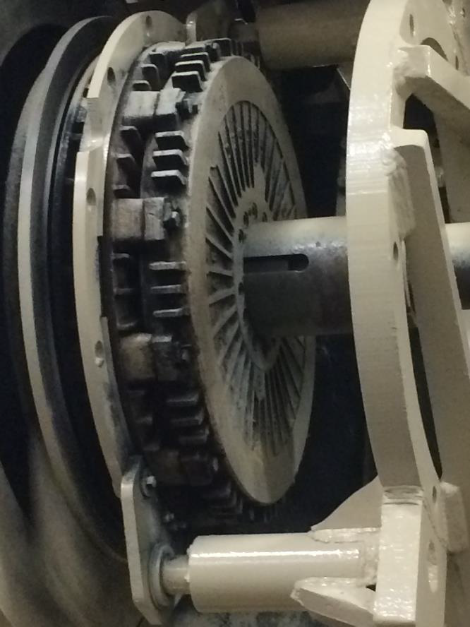
Figure 3: Clutch Conversion Round Pin in Wrong Location
3. Location of Reaction Pins is the third problem with this installation as it effects the way the brake friction plate is supported. It is common for “Modern” clutch/brakes to use two reaction pins to support the brake friction plate. This method has also been used on many of the “Old Style” clutches. Normally with a two point suspension there is one pin that is round and one pin that has flats on it. The pin with the flats is referred to as the square pin. The round pin locates the plate in the proper position in relation to the clutch pressure plates. The square pin keeps the plate from rotating and also allows the friction plate to grow as it gets hot.
In Figure 3 we can see that the round pin is installed at the bottom of the brake assembly. The square pin is installed at the top. This set up will cause problems with brake performance, affect lining life and the overall maintenance required.
If the round pin is installed in the top hole the friction plate hangs freely. This allows the clutch to drive the press without the brake dragging. It also allows the brake to engage smoothly.
When the round pin is in the bottom hole the brake plate can no longer hang freely. When the clutch engages the clearance between the reaction pin and bushing allow the friction plate to flop to one side or the other. The friction surfaces are not parallel to the pressure plate surfaces. The plate drags on the pressure plates causing uneven wear of the friction surfaces. Because the brake plate is cocked the brake does not engage smoothly. This causes reduced brake performance and increases maintenance. As the brake warms up the problems multiply.
It should be noted that normally the holes in the brake bracket are the same size. This allows either pin to fit in the top or bottom holes. So it is important on the initial installation that the round pin is installed in the top hole and the square pin is installed in the bottom hole. Also this procedure needs to be followed if the pins are ever replaced.
Done properly, a clutch conversion is an excellent way to improve the productivity of an older press.
Author: Dave Cooper III CHP Systems, Inc.
Edited By: Mike Gruber, BSME Variegate, Inc.
Copyright Notice:
The materials and services on this site are protected by copyright and/or other intellectual property laws and any unauthorized use of the materials or services at this site may violate such laws. Except as expressly provided herein, Variegate, Inc., CHP Systems and its suppliers do not grant any express or implied right to you under any patents, copyrights, trademarks, or trade secret information with respect to the materials and services.
Except as specifically permitted herein, no portion of the information or documents on this site may be reproduced in any form or by any means without the prior written permission of Variegate, Inc. or CHP Systems.